
Feature
The function of the stop steel plate locking nut (also called the stop steel plate nut or the stop plate nut) is to prevent the nut from loosening, enhance stability and improve safety. The design of the stop steel locking nut contains a metal steel plate that is used to lock the nut and prevent the nut from loosening during vibration or operation to help fix the nut in its installation position, thereby reducing the operating noise and discomfort of the equipment. stability. The stop steel lock nut is suitable for high vibration environments such as aviation, automobiles, and machinery manufacturing. The design of the stop steel lock nut can effectively prevent loosening caused by vibration and ensure the continuous operation of the equipment.
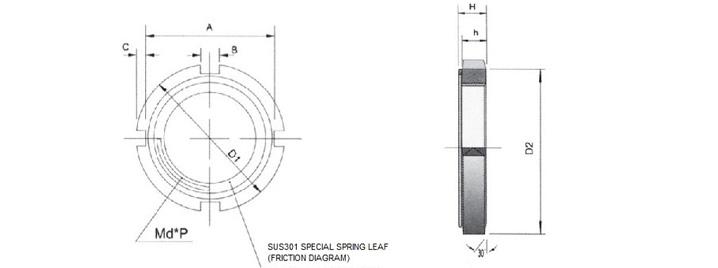
Dimensions
Specification
Unit: mm
| NO. |
Thread (d*P) |
D1 | D2 | A | C | B | h | H | |||||||
| AN00 | M 10*0.75 | 18 | 0 -0.2 | 13 | ±0.2 | 14 (14.4) | 0 -0.2 | 2 (1.8) | 3 | ±0.1 | 4 | 5.2 | ±0.3 | ||
| AN01 | M 12*1 | 22 | 0 -0.2 | 17 | ±0.2 | 18 (18.4) | 0 -0.2 | 2 (1.8) | 3 | ±0.1 | 4 | 5.4 | ±0.3 | ||
| AN02 | M 15*1 | 25 | 0 -0.5 | 21 | 0 -0.5 | 21 (21.4) | 0 -0.5 | 2 (1.8) | 4 | ±0.1 | 5 | 6.5 | ±0.5 | ||
| AN03 | M 17*1 | 28 | 0 -0.5 | 24 | 0 -0.5 | 24 (24.4) | 0 -0.5 | 2 (1.9) | 4 | ±0.2 | 5 | 6.4 | ±0.5 | ||
| AN04 | M 20*1 | 32 | 0 -0.5 | 26 | 0 -0.5 | 28 (28.4) | 0 -0.5 | 2 (1.8) | 4 | ±0.2 | 6 | 7.7 | ±0.5 | ||
| AN05 | M 2.5*1.5 | 48 | 0 -0.5 | 32 | 0 -0.5 | 34 | 0 -0.5 | 2 | 5 | ±0.2 | 7 | 9.1 | ±0.5 | ||
| AN06 | M 30*1.5 | 45 | 0 -0.5 | 38 | 0 -0.5 | 41 | 0 -0.5 | 2 | 5 | ±0.2 | 7 | 9.1 | ±0.8 | ||
| AN07 | M 35*1.5 | 52 | 0 -0.5 | 44 | 0 -0.5 | 48 | 0 -0.5 | 2 | 5 | ±0.2 | 8 | 10.2 | ±0.8 | ||
| AN08 | M 40*1.5 | 58 | 0 -0.5 | 50 | 0 -0.5 | 53 | 0 -0.5 | 2.5 | 6 | ±0.2 | 9 | 11.2 | ±0.8 | ||
| AN09 | M 45*1.5 | 65 | 0 -0.5 | 56 | 0 -0.5 | 60 | 0 -0.5 | 2.5 | 6 | ±0.2 | 10 | 12.5 | ±1.0 | ||
| AN10 | M 50*1.5 | 70 | 0 -0.5 | 61 | 0 -0.5 | 65 | 0 -0.5 | 2.5 | 6 | ±0.2 | 11 | 13.5 | ±1.0 | ||
| AN11 | M 55*2 | 75 | 0 -0.5 | 67 | 0 -0.5 | 69 | 0 -0.5 | 3 | 7 | ±0.2 | 11 | 13.5 | ±1.0 | ||
| AN12 | M 60*2 | 80 | 0 -0.5 | 73 | 0 -0.5 | 74 | 0 -0.5 | 3 | 7 | ±0.2 | 11 | 13.5 | ±1.0 | ||
| AN13 | M 65*2 | 85 | 0 -0.5 | 79 | 0 -0.5 | 79 | 0 -0.5 | 3 | 7 | ±0.2 | 12 | 15 | ±1.5 | ||
| AN14 | M 70*2 | 92 | 0 -0.5 | 85 | 0 -0.5 | 85 | 0 -0.5 | 3.5 | 8 | ±0.2 | 12 | 15 | ±1.5 | ||
| AN15 | M 75*2 | 98 | 0 -0.5 | 90 | 0 -0.5 | 91 | 0 -0.5 | 3.5 | 8 | ±0.2 | 13 | 15.8 | ±1.5 | ||
| AN16 | M 80*2 | 105 | 0 -0.5 | 95 | 0 -0.5 | 98 | 0 -0.5 | 3.5 | 8 | ±0.2 | 15 | 18.6 | ±1.5 | ||
| AN17 | M 85*2 | 110 | 0 -0.5 | 102 | 0 -0.75 | 103 | 0 -0.5 | 3.5 | 8 | ±0.2 | 16 | 19.2 | ±1.5 | ||
| AN18 | M 90*2 | 120 | 0 -0.5 | 108 | 0 -0.75 | 112 | 0 -0.5 | 4 | 10 | ±0.3 | 16 | 20.3 | ±1.5 | ||
| AN19 | M 95*2 | 125 | -0.5 0 | 113 | -0.75 0 | 117 | 0 -0.5 | 4 | 10 | ±0.3 | 17 | 21.3 | ±1.5 | ||
| AN20 | M 100*2 | 130 | 0 -0.5 | 120 | 0 -0.75 | 122 | 0 -0.5 | 4 | 10 | ±0.3 | 18 | 22.3 | ±1.5 | ||